DIY ST-link V2
Hello. I always dreamed to have a st-link debugger, because using stm32discovery for programing other STM32 is not very comfortable (it is taking too many space on desk and too many ugly wires ). I want to show such you a useful and cheap thing for stm32 as DIY ST-link V2 if you will make it as bonus you also will be able to program STM8 microcontrollers. Thanks to russian resourse http://we.easyelectronics.ru/STM32/sozdaem-st-link-v2.html now we have a nice detailed guide how to make your own DIY ST-link V2.
First of all schematic of device.
According to it i created my own PCB in Eagle cad.
Via’s and board I’ve made by my described before technology: http://diygoodies.org.ua/?p=289
After what i soldered all parts. Board became look like that.
Now it is time to upload firmware into our device. We will need a usb-uart adapter, jumper, firmware and “Flash Loader Demonstrator” that you can download from st.com site.

Connecting adapter’s and board pins “TX” “RX” “GND” as in schematics and “Boot 0” jumper according image from original article.
Then you need to upload firware with “Flash Loader Demonstrator” .
After what we need to install drivers for st-link .
And in te end of procedure you must run ST-Link upgrate and upgrate the firware of debugger.
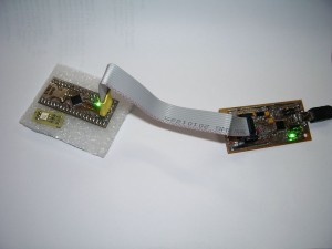
Thats it now you’ve got an DIY ST-link debugger.
And we can program and debug other ST chips.
Then i made a case for it. And glued paper labels.
Progect files in Eagle Cad
[member]
[/member]


Hi
First of all thank you very much for that DIY.
I’ve used a breakout board with a STM32F103, flashed the firmware from your blog (the bin-file) with an existing ST-Link and after reboot the Stm32-Utility detects the STM as a st-link. ok!
BUT when trying to update to the newest firmware V2.J19.S4 I get an error:
“update error, please ty again”
Any idea ?
Thanx
Thomas
Well did you check schematics is it the same as in your board? Especially USB part. Quartz frequency is the same? What is the full name of your MCU.